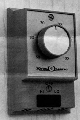
Optional thermostat control is now being offered for use with all models of recreational vehicle ventilators as shown in the photograph. The aftermarket RV installation is normally made in a closet wall or in any convenient wall location approximately four feet above the floor, using a standard 2″ x 4″ electrical outlet box. If the difficulty is encountered in drawing the required wire leads through the ceiling and wall, or wall installation is impractical, the thermostat may be ceiling mounted adjacent to the ventilator for simplified installation.

For automatic RV comfort, the Model RVT2 Thermostat Control is provided with a two-speed three-position operation selector switch. The HI and Lo Switch Position provides automatic fan operation with the fan operating anytime the temperature inside the RV is above the setpoint temperature. This position also provides an automatic ventilator shut off, an especially desirable feature while sleeping. Many dealers tell us how they install the ventilator on their lot demonstrators to quickly pull the heat and odors out when showing a closed up RV to a prospect. There’s nothing that cools a prospect more than the heat and eye irritation of a closed up new RV unit in the summer.
The Off Position provides power off setting to eliminate the fan from accidentally operating while the RV is completely closed up or is in storage.
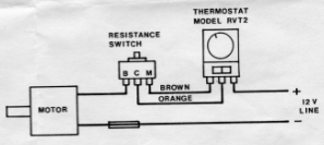
HI-LO WIRING DIAGRAM – THERMOSTAT MODEL RVT2
(Alternate Hi-Medium setting can be obtained by turning the resistance switch one position clockwise.
Motor lead to “B” terminal on resistance switch.
Thermostat orange leads to a “C” terminal on resistance switch.
Thermostat brown lead to “M” terminal on resistance switch.
Motor leads to no power lead.
Thermostat black lead to + power lead.


