The mechanics of a turbocharger are closely related to the mechanics of a jet engine. If you were to modify the turbo so that the compressor outlet fed the turbine inlet you would be on your way to making a jet engine. A turbo’s relationship with a jet engine should give you some idea of the potential of turbochargers.
A turbocharger harnesses the wasted energy of exhaust gases exiting the engine to spin a turbine that compresses the intake air charge. Exhaust gases are directed into the turbocharger through the square inlet in the exhaust housing of the turbo (shown in the bottom left of the above picture).
The exhaust flows through the exhaust housing spinning the exhaust turbine. After going through the exhaust housing, the gasses flow out through the exhaust housing outlet (middle left in the picture).
The turbine is connected to the compressor wheel on the intake side of the turbo through the center bearing housing. The center housing will have ports for oil to flow in to and out of to lubricate and cool the shaft, and it may or may not have ports for water to go in to and out of.
The above picture does not show ports for water. Fresh air is brought into the turbocharger through the air inlet (middle right in the picture). The air is compressed by the compressor and the now pressurized air flows out through the compressor housing. Note: The picture above shows a turbocharger with an internal wastegate.

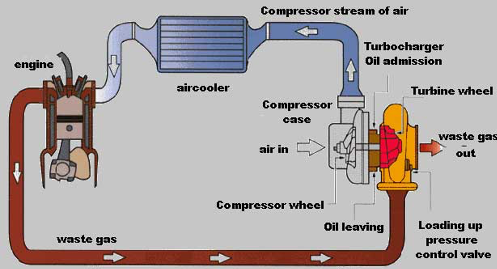
Above we see the basic layout of the components of a turbocharger system.
Exhaust gases leave the engine via a turbo manifold, this replaces the stock exhaust manifold or header. One thing missing from the above diagram is an external wastegate. The wastegate is used to control boost levels by allowing exhaust gasses to bypass the turbo, thereby decreasing the volume of exhaust available to spin the turbo’s turbine.
After moving through the turbo, exhaust gasses exit the turbo through a downpipe which connects to the rest of the exhaust system. Fresh air, after being compressed by the turbo, passes through some intake piping and into an intercooler (‘air cooler’ in the above diagram).
An intercooler works exactly as a radiator except pressurized air passes through it instead of water. This cools the pressurized intake air charge. This is necessary because when air is pressurized it heats up. Another component missing in the above diagram is a blow-off valve (BOV). The blow-off valve vents pressurized air when the throttle plate is closed. This prevents a pressure surge from building up in the system and possibly damaging the compressor wheel and the turbo’s bearings. Another component not shown is a pop-off valve (POV). A POV is a safety valve that opens, and stays open until manually closed, when a preset boost level is reached, venting most if not all pressurized air. This prevents an over-boost situation that may occur if there is a wastegate or boost controller failure.