by Allison Transmissions
1.0 PURPOSE
In order to satisfy the different needs and desires of operators in a wide variety of applications, vocations, and vehicle configurations, several types of retarder apply systems are offered for Allison transmissions with WTEC-III controls. Although certain types of apply systems may not be recommended for specific vocations — because the retarder performance may not be appropriate for the class or type of vehicle, installation may be cumbersome, or some other factor — a viable choice of two or more application types is available for most vehicles. The purpose of this document is to define each available retarder application system, describe factors that influence the selection of each type, and provide basic guidance for the installation of each type of system.
2.0 RETARDER APPLY SYSTEMS
Several basic retarders apply system designs that are available and supported by Allison. A brief overview of each type is summarized in Section 3.0. Additional details of each are summarized on the individual schematics on the pages which follow.
Allison parts described in this section are available through your order correspondent at the Allison Parts Distribution Center (P.D.C.). If you do not have an order correspondent, contact Allison P.D.C. per instructions in the Support Equipment section of any Allison Transmission Installation Manual.
2.1 WHEN IS THE RETARDER APPLIED?
The retarder applies the system does not actuate the retarder directly. The application system provides a means for the operator to request a desired level of retardation. This request is processed by the Electronic Control Unit (ECU) in conjunction with other input data which defines the current operating status of the transmission and vehicle. After evaluating the appropriate input data, the ECU determines
(1) if the retarder should be applied, and (2) at what level of retarder capacity. The ECU then commands the retarder application accordingly.
NOTE: The following applies conditions must be met before the ECU will command activation of the retarder:
• The “Retarder Enable” switch must be ON, and
• The engine must be at closed throttle, and
• Transmission output speed must be above a preset (calibration) value.
2.2 TAKING ADVANTAGE OF THE AUTOMATIC APPLY FEATURE
Several of the recommended retarder apply systems automatically activate the retarder whenever the ECU applies conditions (section 2.1) are met. Depending upon the control system which is chosen, the retarder may be applied at full capacity (100%), or at a lesser capacity level.
Throttle position is a significant, operator-controllable input signal which determines whether or not the retarder will be actuated. Assuming that the other factors (retarder switch and output speed) favor actuation of the retarder, a skilled operator may use the throttle pedal to command three distinct modes for operating the vehicle:
• to accelerate the vehicle, depress throttle
• to slow the vehicle, release the throttle fully to the closed throttle position, or
• to coast the vehicle, apply the throttle lightly (keeping it above closed throttle, which would apply the retarder), but at a level which is too low to accelerate the vehicle.
2.3 INTEGRATING RETARDER CONTROLS WITH VEHICLE BRAKE SYSTEMS
Several retarders apply systems that are designed to apply the retarder based on the status (apply pressure) of the vehicle air-brake system. A variety of pressure switches (actuated at different brake system pressures) are available for use in these systems, either individually or in combination. To design a retarder control system that utilizes one or more brake system pressure switches requires a thorough understanding of the brake system operation (e.g. apply pressures) in order to properly integrate the retarder application schedule with the vehicle braking function. In general, any system which activates the retarder before the vehicle service brakes are applied will improve the life of the service brakes.
3.0 RETARDER APPLY SYSTEMS
1. MANUAL APPLY WITH SEPARATE RETARDER PEDAL — Once the application conditions are met and the retarder apply system is activated, retarder capacity is infinitely variable between full-off (0%) and full-on (100%), depending upon the apply position of the retarder foot pedal.
2. AUTOMATIC FULL-ON APPLY AT CLOSED THROTTLE — Once the application conditions are met and the retarder applies the system is activated, the retarder is automatically applied at full-on (100%) capacity.
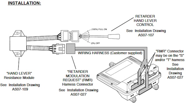
3. AUTOMATIC APPLY WITH HAND LEVER — Once the apply conditions are met and the retarder apply system is activated, the retarder is automatically applied at the capacity selected on the retarder hand lever control. Capacity levels are approximately: 0%, 17%, 33%, 50%, 63%, 83%, 100%.
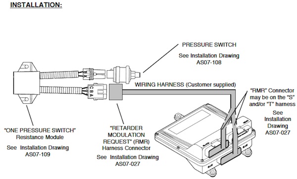
4. ONE-STEP APPLY WITH BRAKE PEDAL — Once the application conditions are met and the retarder apply the system is activated, the retarder is applied at full-on (100%) capacity whenever the vehicle brake apply pressure reaches the level of the apply pressure switch.
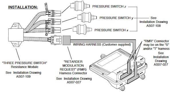
5. THREE-STEP APPLY – BRAKE PRESSURE SWITCHES — Once the apply conditions are met and the retarder apply system is activated, the retarder is applied when the vehicle brakes are applied. Three separate levels of retarder capacity (approximately 33%, 67%, 100%) are commanded as brake demand (brake system pressure) is increased.
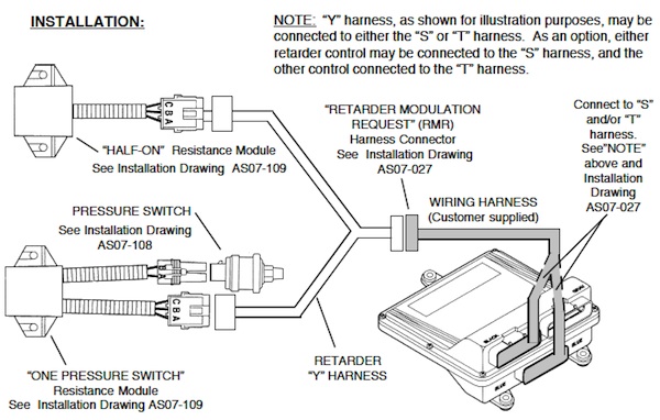
6. AUTOMATIC ONE-HALF APPLY, PLUS BRAKE PRESSURE SWITCH — Once the application conditions are met and the retarder apply the system is activated, the retarder is applied at half-on (50%). Retarder capacity increases to full-on (100%) when the vehicle brakes are applied.
7. AUTOMATIC ONE-THIRD APPLY, PLUS BRAKE PRESSURE SWITCHES — Once the application conditions are met and the retarder applies the system is activated, the retarder is applied at one-third capacity (33%). Retarder capacity increases to two-thirds (67%) capacity when the vehicle brakes are initially applied, then to full-on (100%) when a higher level of brake apply is detected.
8. AUTOMATIC APPLY WITH HAND LEVER, PLUS FULL-ON WITH BRAKES — Once the application conditions are met and the retarder applies system is activated, the retarder is automatically applied at the capacity selected on the retarder hand lever control. Capacity levels are approximately: 0%, 17%, 33%, 50%, 63%, 83%, 100%. If the retarder has been automatically applied (as above) at a capacity less than full-on (100%), it will subsequently be applied full-on when the vehicle brakes are applied.
9. MANUAL APPLY WITH RETARDER PEDAL, PLUS FULL-ON WITH BRAKES —
Once the application conditions are met and the retarder apply system is activated, retarder capacity is infinitely variable between full-off (0%) and full-on (100%), depending upon the application position of the retarder foot pedal.
Independently from the above, once the application conditions are met and the retarder apply system is activated, the retarder is applied at full-on (100%) capacity whenever the vehicle brakes are applied.
This control system is especially useful in a vehicle that uses the retarder for downhill speed control (with modulated partial capacity via retarder pedal), plus full-capacity (full-on with brakes) during stop-and-go driving.
10. AUTOMATIC APPLY WITH HAND LEVER, PLUS THREE-STEP APPLY WITH BRAKES
Once the application conditions are met and the retarder application system is activated, the retarder is automatically applied at the capacity selected on the retarder hand lever control. Capacity levels are approximately: 0%, 17%, 33%, 50%, 63%, 83%, 100%.
Independently from the above, once the application conditions are met and the retarder apply system is activated, the retarder is applied when the vehicle brakes are applied. Three separate levels of retarder capacity (approximately 33%, 67%, 100%) are commanded as brake demand (brake system pressure) is increased.
This control system is useful in a vehicle that uses the retarder for downhill speed control (with selected partial capacity via retarder hand lever), plus increasing retarder capacity as brake pressure is increased during stop-and-go driving.
4.0 RECOMMENDED CONTROL SYSTEMS
On the pages which follow, several detailed items relating to each retarder control system configuration are presented. An individual page is dedicated to each retarder control configuration. On each page, the following topics are discussed:
• Description of operation. Note that these descriptions assume that several operating conditions are satisfied. If these conditions do not exist, the ECU will not activate the retarder, even though it may be requested by the operator. For a description of these conditions, see Section 2.1.
• Advantages and disadvantages of this configuration, as compared to others
• List of components required for this configuration
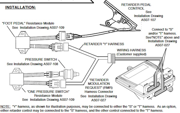
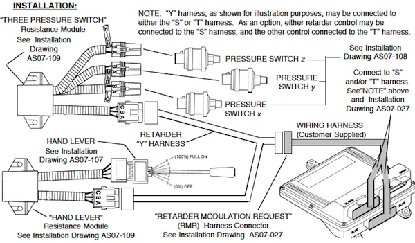
• System schematic for installation
5.0 RETARDER CONTROL SYSTEM COMPONENT PART NUMBERS
The following Allison part numbers are believed to be accurate as of the publication date of this document. To verify the accuracy of part numbers or availability of parts, consult your order correspondent at the Allison Parts Distribution Center (P.D.C.). If you do not have an order correspondent, contact Allison P.D.C. per instructions in the Support Equipment section of any Allison Transmission Installation Manual.
| Component | Allison Part Number |
| Operator Interface Controls: | |
| Retarder pedal _ 35_ pedal travel | 29538485 |
| Retarder pedal _ 45_ pedal travel | 29538486 |
| Hand lever _ 120 mm (4.7 in) length | 29521372 |
| Hand lever _ 200 mm (7.9 in) length | 29522721 |
| Pressure Switches: | |
| 2 psi switch | 29506478 |
| 4 psi switch | 29511307 |
| 7 psi switch | 29511308 |
| 10 psi switch | 29511309 |
| Resistance Module for: | |
| Retarder pedal | 29509895 |
| Hand lever | 29506474 |
| Full-on | 29506470 |
| Half-on | 29509894 |
| One pressure switch | 29506471 |
| Auto 1/3 apply + two pressure switches | 29511320 |
| Three pressure switches | 29511306 |
| Retarder Modulation Request (RMR) “Y” Harness: | 29521875 |
WTEC-III — RETARDER CONTROLS
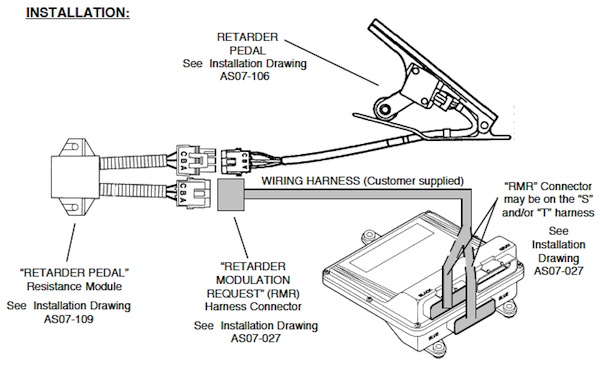
MANUAL RETARDER APPLY WITH SEPARATE RETARDER PEDAL DESCRIPTION:
Conditions must be appropriate for retarder operation. See section 2.1of text. When the retarder apply system is operational, retarder capacity is infinitely variable between full-off (0%) and full-on (100%), depending upon the position of the operator’s control (retarder foot pedal).
ADVANTAGES:
• Retarder capacity is infinitely variable
• Retarder control does not have to be matched with the configuration of the brake system (timing, brake apply pressures, etc.)
• Since retarder is not applied until the retarder pedal is pushed, the vehicle may be allowed to coast at closed throttle without the retarder being applied.
DISADVANTAGES:
• Space claim required for two operator pedals – one for brake, one for retarder
• Not easy to maintain smooth deceleration when transitioning from retarder operation to brake
COMPONENTS: (See Section 5.0 for source information)
1. Foot pedal retarder control
2. “Retarder Pedal” resistance module
AUTO APPLY (FULL ON) AT CLOSED THROTTLE
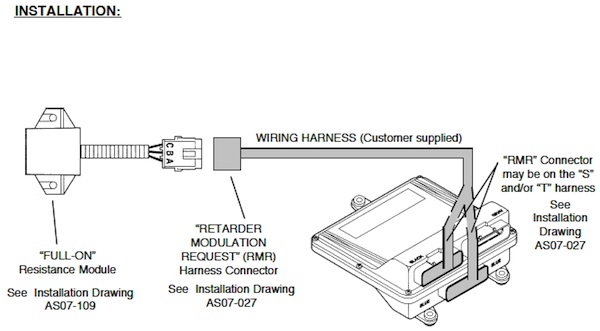
DESCRIPTION:
Conditions must be appropriate for retarder operation. See section 2.1of the text. When the retarder application system is operational, the retarder is automatically applied at full-on (100%) capacity.
ADVANTAGES:
• Ease of installation. The fewest number of add-on components
• Maximizes retarder-on time
DISADVANTAGES:
• Inhibits coasting at closed throttle. Depending upon the amount of coast time in the duty cycle, this apply system may adversely affect fuel economy.
• The driver has no facility to modulate the retarder braking effect — it is either off or full-on.
COMPONENTS: (See Section 5.0 for source information)
1. “Full-On” resistance module
AUTOMATIC APPLY WITH HAND LEVER
DESCRIPTION:
Conditions must be appropriate for retarder operation. See section 2.1of the text. When the retarder application system is operational, the retarder is automatically applied at the capacity selected on the retarder hand lever control.
Capacity levels selectable on the lever are:
| Lever Position* | Approx. Retarder Capacity |
| Off | 0 % |
| 1 | 17 % |
| 2 | 33 % |
| 3 | 50 % |
| 4 | 67 % |
| 5 | 83 % |
| 6 | 100 % |
* NOTE: A pin, provided with each lever, may be inserted at any lever position (except “Off”) to limit handle travel at or beyond that position. For example, if the lever is placed in a high position and the pin is inserted at position 3, only positions 4, 5, and 6 may be selected. Conversely, if the lever is in a low position when “pinned” at position 3, only positions Off, 1, and 2 may be selected.
ADVANTAGES:
• Permits selection of various levels of retardation, which are driver-selectable
• The lever may be left in the desired position (capacity) and switched on/off automatically by ECU as conditions dictate.
DISADVANTAGES:
• If the lever is left on and ECU is used for automatic on/off control, the vehicle does not have the capability to the coast at closed throttle – which may have a negative impact on fuel economy. Driver training is required to optimize both brake savings and fuel economy.
COMPONENTS: (See Section 5.0 for source information)
1. Hand lever retarder control, with blocking pin
2. “Hand Lever” resistance module
FULL APPLY WITH BRAKE PEDAL (SINGLE PRESSURE SWITCH)
DESCRIPTION:
Conditions must be appropriate for retarder operation. See section 2.1 of the text.
When the retarder application system is operational, the retarder is applied at full-on (100%) capacity whenever the service brakes are applied. The application of the service brake is detected by the presence of pressure in the service brake system in excess of x psi.
ADVANTAGES:
• Ease of installation. A small number of add-on components.
• High retarder usage.
• As compared to configuration 2 (Auto Apply at Closed Throttle), this configuration does permit the vehicle to coast without the retarder being applied.
DISADVANTAGES:
• The driver has no facility to modulate the retarder braking effect — it is either off or full-on.
COMPONENTS: (See Section 5.0 for source information)
1. One brake system pressure switch (choose one from list):
| (a) | x = 2 psi | |
| (b) | x = 4 psi | |
| (c) | x = 7 psi | |
| (d) | x = 10 psi | (Do not use with S-cam type service brakes) |
2. “One Pressure Switch” resistance module
THREE-STEP APPLY WITH BRAKE PRESSURE DESCRIPTION:
Conditions must be appropriate for retarder operation. See section 2.1of the text. When the retarder apply system is operational: • Retarder is applied at one-third (33%) capacity when x psi apply pressure is detected in the service brake system. • Retarder capacity is increased to two-thirds (67%) capacity when y psi applies pressure is detected in the service brake system. • Retarder capacity is increased to full-on (100%) capacity when z psi applies pressure is detected in the service brake system.
ADVANTAGES:
• It provides increasing levels of retardation in proportion to the operator’s demand for more braking.
• Since retarder is not applied until pressure is detected in the service brake system, the vehicle may be allowed to the coast at closed throttle without the retarder being applied.
DISADVANTAGES:
• Requires a thorough understanding of the vehicle brake system operation (pressures, timing) to optimize this configuration to the brake system.
COMPONENTS: (See Section 5.0 for source information)
1. A combination of three brake pressure switches (choose from list):
| (a) | x = 2 psi, y = 4 psi, z = 7 psi | |
| (b) | x = 2 psi, y = 7 psi, z = 10 psi | (Do not use with S-cam type service brakes) |
| (c) | x = 4 psi, y = 7 psi, z = 10 psi | (Do not use with S-cam type service brakes) |
2. “Three Pressure Switch” Resistance Module
AUTOMATIC ONE-HALF APPLY PLUS BRAKE PRESSURE SWITCH
DESCRIPTION:
Conditions must be appropriate for retarder operation. See section 2.1of text.
When the retarder apply system is operational:
• Retarder is applied at one-half (50%) capacity whenever apply conditions are met
• Retarder capacity is increased to full-on (100%) when the service brakes are applied (pressure in the service brake system exceeds x psi as detected by brake pressure switch).
ADVANTAGES:
• Maximizes retarder-on time, although initial retarder applies at half capacity provides less aggressive initial response than application at full capacity.
DISADVANTAGES:
• Inhibits coasting at closed throttle. Depending upon the amount of coast time in the duty cycle, this apply system may adversely affect fuel economy.
COMPONENTS: (See Section 5.0 for source information)
1. One brake pressure switch (choose from list):
| (a) | x = 2 psi | |
| (b) | x = 4 psi | |
| (c) | x = 7 psi | |
| (d) | x = 10 psi | (Do not use with S-cam type service brakes) |
2. “One Pressure Switch” Resistance Module
3. “Half-On” Resistance Module
AUTOMATIC ONE-THIRD APPLY PLUS BRAKE PRESSURE SWITCHES
DESCRIPTION:
Conditions must be appropriate for retarder operation. See section 2.1of the text.
When the retarder apply system is operational:
• Retarder is applied at approximately one-third (33%) capacity whenever apply conditions are met
• Retarder capacity is increased to approximately two-thirds (67%) capacity when x psi applies pressure is detected in the service brake system.
• Retarder capacity is increased to full-on (100%) capacity when y psi applies pressure is detected in the service brake system.
ADVANTAGES:
• Maximizes retarder-on time, although initial retarder applies at one-third capacity provides less aggressive initial response than application at full capacity.
DISADVANTAGES:
• Inhibits coasting at closed throttle. Depending upon the amount of coast time in the duty cycle, this apply system may adversely affect fuel economy.
COMPONENTS: (See Section 5.0 for source information)
1. A combination of two brake pressure switches (choose from list):
| (a) | x = 2 psi, y = 4 psi | (Allison “first choice”) |
| (b) | x = 2 psi, y = 7 psi | |
| (c) | x = 2 psi, y = 10 psi | (Do not use with S-cam type service brakes) |
| (d) | x = 4 psi, y = 7 psi | |
| (e) | x = 4 psi, y = 10 psi | (Do not use with S-cam type service brakes) |
| (f) | x = 7 psi, y = 10 psi | (Do not use with S-cam type service brakes) |
2. Resistance Module for Auto 1/3 apply + two pressure switches
AUTOMATIC APPLY W/ HAND LEVER, PLUS FULL-ON W/ BRAKES
DESCRIPTION:
Conditions must be appropriate for retarder operation. See section 2.1of text.
When the retarder application system is operational, the retarder is automatically applied at the capacity selected on the retarder hand lever control. Capacity levels selectable on the lever are 0%, 17%, 33%, 50%, 67%, 83%, and 100%. * See “NOTE” in the Components section below.
When the retarder application system is operational and x apply pressure is detected in the service brake system, the retarder will be applied full-on (100%). This occurs whether the retarder was not applied or was partially applied when the brake system pressure was detected.
ADVANTAGES:
• Permits selection of various levels of initial retardation, which are driver-selectable
• The lever may be left in the desired intermediate capacity position and switched on/off automatically by ECU as conditions dictate. Additional (full) retarder capacity is available when the brake system is activated.
DISADVANTAGES:
• If the lever is left on, ECU provides automatic on/off control at the capacity selected on the lever. The vehicle does not have the capability to coast at closed throttle – which may have a negative impact on fuel economy.
Driver training is required to optimize both brake savings and fuel economy.
COMPONENTS: (See Section 5.0 for source information)
1. Hand lever retarder control *
2. “Lever” resistance module
3. One brake pressure switch (choose from list):
(a) x = 2 psi
(b) x = 4 psi
(c) x = 7 psi
(d) x = 10 psi (Do not use with S-cam type service brakes)
* NOTE: A pin, provided with each lever, may be inserted at any lever position (except “Off”) to limit handle travel at or beyond that position. For example, if the lever is placed in a high position and the pin is inserted at position 3, only positions 4, 5, and 6 may be selected. Conversely, if the lever is in a low position when “pinned” at position 3, only positions Off, 1, and 2 may be selected
4. “One Pressure Switch” resistance module
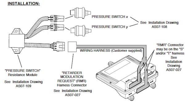
MANUAL APPLY WITH FOOT PEDAL, PLUS FULL-ON W/ BRAKES
DESCRIPTION:
Conditions must be appropriate for retarder operation. See section 2.1of the text.
When the retarder application system is operational, retarder capacity is infinitely variable between full-off (0%) and full-on (100%), depending upon the position of the operator control (retarder pedal).
If the retarder has been automatically applied (above) at a capacity less than full-on (100%), it will subsequently be applied full-on when x apply pressure is detected in the service brake system.
ADVANTAGES:
• Retarder capacity is infinitely variable with the pedal. Additional (full) retarder capacity is available when the brake system is activated.
• Retarder control does not have to be matched with the configuration of the brake system (timing, brake apply pressures, etc.) for intermediate retarder capacities.
• Since retarder is not applied until the retarder pedal is pushed, the vehicle may be allowed to coast at closed throttle without the retarder being applied.
DISADVANTAGES:
• Space claim required for two operator pedals – one for brake, one for retarder
COMPONENTS: (See Section 5.0 for source information)
1. Retarder Pedal retarder control
2. “Retarder Pedal” resistance module
3. One brake pressure switch (choose from list):
(a) x = 2 psi
(b) x = 4 psi
(c) x = 7 psi
(d) x = 10 psi (Do not use with S-cam type service brakes)
4. “One Pressure Switch” resistance module
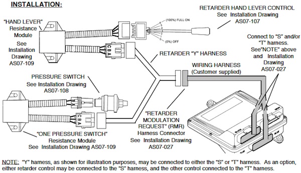
AUTOMATIC APPLY WITH HAND LEVER, PLUS THREE-STEP APPLY WITH BRAKES
DESCRIPTION:
Conditions must be appropriate for retarder operation. See section 2.1of the text.
When the retarder application system is operational, the retarder is automatically applied at the capacity selected on the retarder hand lever control. Capacity levels selectable on the lever are 0%, 17%, 33%, 50%, 67%, 83%, and 100%.
* See “NOTE” in the Components section below.
If the retarder has been automatically applied (above) at a capacity less than full-on (100%), it will subsequently be applied to the highest level requested from either input when apply pressure is detected in the service brake system.
ADVANTAGES:
• Permits selection of various levels of initial retardation, which are driver-selectable with the lever
• The lever may be left in the desired intermediate capacity position and switched on/off automatically by ECU as conditions dictate. Additional (full) retarder capacity is available when the brake system is activated.
DISADVANTAGES:
• If the lever is left on, ECU provides automatic on/off control at the capacity selected on the lever. The vehicle does not have the capability to coast at closed throttle – which may have a negative impact on fuel economy. Driver training is required to optimize both brake savings and fuel economy.
• Requires a thorough understanding of the vehicle brake system operation (pressures, timing) to integrate and optimize this configuration to the brake system
• Installation complexity
COMPONENTS: (See Section 5.0 for source information)
1. A combination of three brake pressure switches (choose from list):
(a) x = 2 psi, y = 4 psi, z = 7 psi
(b) x = 2 psi, y = 7 psi, z = 10 psi **
(c) x = 4 psi, y = 7 psi, z = 10 psi **
2. Hand lever retarder control*
3. “Lever” resistance module
4. “Three Pressure Switch” resistance module
* NOTE: A pin, provided with each lever, may be inserted at any lever position (except “Off”) to limit handle travel at or beyond that position. For example, if the lever is placed in a high position and the pin is inserted at position 3, only positions 4, 5, and 6 may be selected. Conversely, if the lever is in a low position when “pinned” at position 3, only positions Off, 1, and 2 may be selected.
** Do not use with S-cam type service brakes
